 HW-8 Mods
HW-8 Mods
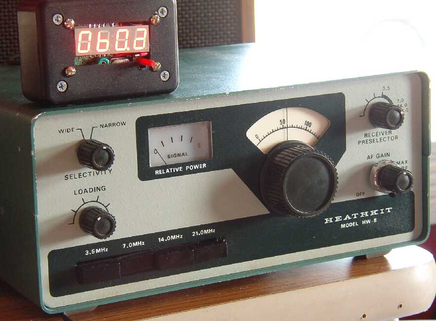
Normally I don't want to modify vintage gear. I am making an exception on the HW-8 because I am more interested in USING it than keeping it original.
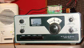
One of the simplest mods was done for me - an SO-239 antenna connector was added. I disconnected the original RCA phono jack and later utilized it for output to my Digital Display.
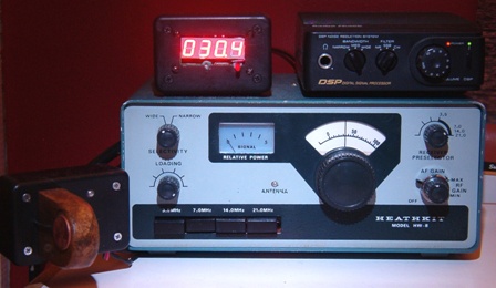 |
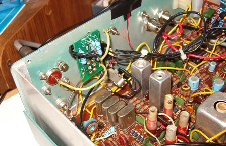
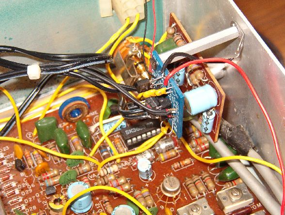
Heath HW8 Digital Display by Steve Weber - KD1JV Radio Shack 21-543 DSP amplified speaker TouchKeyer and Paddle N7VE SWR Indicator |
Radio Shack 21-543 DSP amplified speaker
My latest solution for selectivity on the HW8 is a Radio Shack DSP. These can be found for about $20 on eBay or at hamfests. On the HW8 we don't care much about the SSB or Noise Reduction modes but the CW mode works well. I have used this setup during CW contests and the DSP filter really helps.
The HW8 barely has enough audio to drive it, but, with a
simple modification, you can just about double the output of audio.
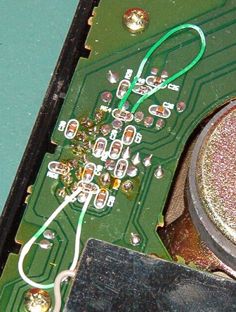
The mod is to solder a jumper across R54 and R57 on the bottom side of the PCB. These are surface mount resistors and the part numbers are 'close to' the resistors, but not right next to them. Get some very thin solid wire (28 ga.) and make each jumper about 2 inches long. Tin each end and then tack it across the resistors. The jumper then lays flat on the PCB.
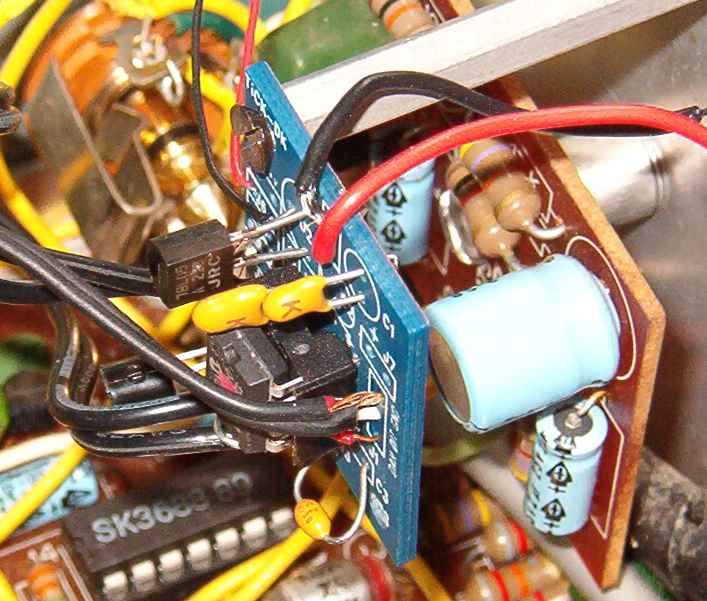
Here's an explanation and credit :
The September 1998 Hints newsletter from the American Radio Relay League (ARRL) has the following modification:
Louder DSP with the RS 21-543 Box
Michael, N4TMI, has a quick fix for anyone trying to get more volume out of a Radio Shack 21-543 DSP box:
The cure is simple. The gain of the audio amplifier can be doubled by soldering wire jumpers across R54 and R57. These are clearly labeled 100-ohm chip resistors on the underside of the circuit board. According to the manufacturer's data sheet, the KIA7227CP audio amp chip does not require these components. Their only purpose is to reduce gain, apparently a bad idea in this situation. After the mod, it's much easier to get room-filling volume from a speaker. Sound quality is excellent, and digital signal processing is unaffected.
--Michael A. Covington, N4TMI, 285 St George Drive, Athens, GA 30606; e-mail mc@ai.uga.edu
SWR Indicator - from
www.qrpkits.com
 |
 |
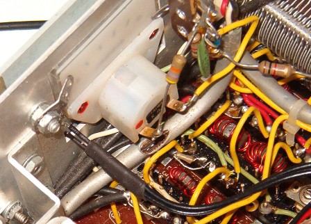
| PCB mounted just to right of antenna connector. Note - If not using coaxial cable, be sure to put a ground on the board. | LED epoxied into small hole drilled into front panel. This hole is right in the open area of the sub-panel at the bottom of the square hole for the meter. Be sure to get it lined up right! |
 |
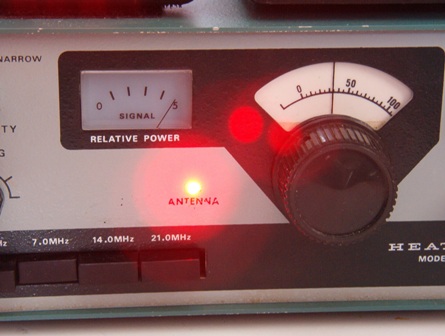 |
| Detail of inside view of LED coming thru sub-panel under meter. Use heat shrink on LED legs to prevent shorts | LED indicator with high SWR. Proper tuning of ATU will extinguish LED |
Thoughts on this project :
My small tuners (Dentron Jr. Monitors) don't have a metering circuit that gives
indication of proper match - especially at QRP levels. If I put a QRP
tuner circuit into the tuner - it becomes a QRP tuner only. I wanted the
SWR indicator in the HW8 so that it is always there regardless on which tuner
(if any) is behind the rig. At QRP levels there is a common and simple
bridge circuit that can be switched in and out and allows you to adjust the
match to balance the bridge and extinguish an LED when the circuit is balanced.
You can scratch-build the circuit but you can buy a small kit including all the
parts for $12 from
www.qrpkits.com
- well worth the money.
The only thing that didn't work for me was the fact that the kit is all on one board - including the IN/OUT switch and LED indicator. There is not much room on the front panel of the HW8, plus I wanted to keep it near the antenna connection. At first I was going to use a DPDT relay to switch it in and out with a switch and LED on the front panel. I decided instead to mount the board and switch right next to the antenna connector and just remote the LED to the front panel. The switch is easily accessible from the front side as it is only about an inch from the top.
This circuit works great at the 2 watt level! Since I
can't see the rear panel mounted switch, I have to check to make sure that it is
not in the TEST position. Other than that, it is a great solution.
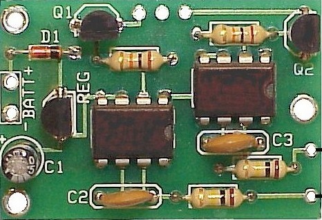
TiCK-1 Keyer
 |
 |
| TiCK Keyer mounted on standoff near audio amp. | Closeup of TiCK Keyer |
Since I have about $100 in the HW-8 I don't want to 'over-improve' it so I chose a TiCK-1 Keyer kit that costs $16. It is a very basic keyer that works great and is easy to learn to use. I mounted the paddle jack and keyer program button on the rear panel above the standard key jack. I mounted the keyer PCB on a standoff next to the audio amp.
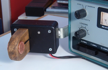
TouchKeyer / Penny Pincher
Paddle
 After installing the Tick Keyer, I decided
that I needed a quality paddle that didn't weigh as much as the HW8. I was
intrigued with the TouchKeyer displays that I had seen at Hamfests, so I thought
that I'd give it a try. The kit is about $20 and you can buy them already
assembled. I think that the IC chips are normally used for 'Touch Lamp'
control.
After installing the Tick Keyer, I decided
that I needed a quality paddle that didn't weigh as much as the HW8. I was
intrigued with the TouchKeyer displays that I had seen at Hamfests, so I thought
that I'd give it a try. The kit is about $20 and you can buy them already
assembled. I think that the IC chips are normally used for 'Touch Lamp'
control.
I stole a page from Elecraft and mounted my paddle and TouchKeyer right on the HW8. See the picture above - it is mounted on the left side of the HW8 with a sturdy bracket. The paddle presents itself at a 45 deg. angle like the Elecraft paddles.
I mounted the tiny PCB inside a small Radio Shack project box and mounted a small block of wood to the front. I soldered some small wire to 2 pennies and epoxied them to the wood block out near the front edge. I picked up power from the rig so i am not concerned about power consumption. If you wanted to battery-power it, you might want an ON/OFF switch and maybe a blinking LED to remind you that it is on. I measured the current at 1.4ma.
I found the keying to very sensitive - almost too sensitive. One of the TouchKey users said that he could operate with gloves on. I don't plan on operating with gloves on so, per the instructions, I increased the size of the 2 inline resistors from 100k to 200k and find that I seem to have fewer errors from not getting my fingers away from the contacts. I am now pleased with the keying.
For more info on TouchKeyers visit:
http://www.cwtouchkeyer.com/HOME.htm
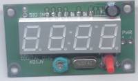
Digital Frequency Display
|
|
|
| Display Board temporarily connected and battery powered | Display mounted in small project box with power from HW-8. Just need some flat black paint on shiny screw heads. |
 Keeping
with the theme that I don't want to 'over-improve' the HW-8, I looked for
some sort of digital dial to help with the HW-8 dial accuracy. Small
Wonder Labs makes the "Freq Mite" that reads the frequency out in CW when you
press a button, but I wanted a display. At one time, plus or minus 2-3 khz
was OK but I have become spoiled with digital frequency display and accuracy.
I found that
Steve Weber-KD1JV
produces
a Frequency Counter/Digital Display for $35 dollars. The challenge is that
it is made with Surface Mount Technology parts. I wasn't sure if I was up
to the challenge but I ordered one anyway.
Keeping
with the theme that I don't want to 'over-improve' the HW-8, I looked for
some sort of digital dial to help with the HW-8 dial accuracy. Small
Wonder Labs makes the "Freq Mite" that reads the frequency out in CW when you
press a button, but I wanted a display. At one time, plus or minus 2-3 khz
was OK but I have become spoiled with digital frequency display and accuracy.
I found that
Steve Weber-KD1JV
produces
a Frequency Counter/Digital Display for $35 dollars. The challenge is that
it is made with Surface Mount Technology parts. I wasn't sure if I was up
to the challenge but I ordered one anyway.
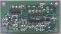
Well it took the better part of a day to learn how to mount these tiny parts on the PCB. I took my time and had to work under a light/magnifier in order to even read the component numbers but I managed to get it all together and the soldering looked OK. The circuit worked as promised - I was thrilled.
Next step was to permanently install it. I went back and forth trying to figure out how and where to to mount it. If you know about the HW-8 you also know that there just is not a lot of space on the front panel. So, I decided to outboard it in a small project box.
I capacitor couple across R53 in the HW-8. That is essentially the output of the Mixer Amp and the input of the driver. I used the 4.7pf capacitor supplied with the kit to couple and it has proven to be enough coupling to drive the display on and across all bands with no sign of loading the circuit. I took the output to the abandoned RCA Phone antenna connector with RG174U. The counter has a 14 inch length of the RG174U terminated in a phono connector.
I also added a coaxial power jack on the HW-8 that provides switched power out to the display. I calibrated the counter against my TS440 that is calibrated to WWV.
So now I have a nice digital display and I am no longer afraid of SMT projects. What's next?